3.1 Principle of programming
3.2 Ready to use Fraction collector with the supplied tube racks
3.3 Programming the OMNICOLL for any tube racks or recipients
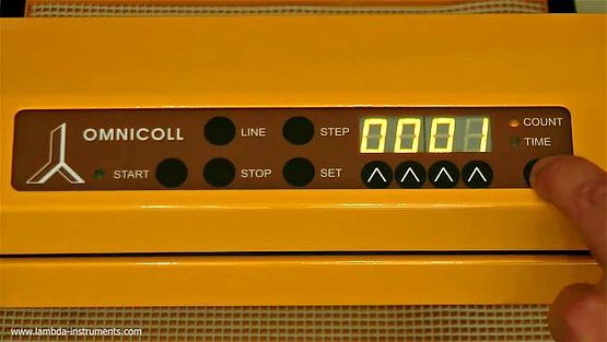
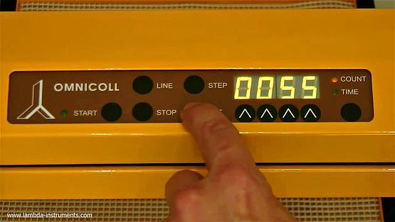
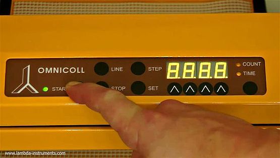
3.4 Control Panel of OMNICOLL Fraction Collector
3.5 Fraction collection according to the volume
3.6 Calibration of the peristaltic pump and the OMNICOLL
3.7 Fraction collection with a time interval in-between fractions (“high”)
3.8 Multi-channel fraction collection – multiple stream sampling
3.9 How to increase the capacity of the fraction collector?
3.1 Principle of programming
Laboratory practice shows that programming of instruments equipped with microprocessors are not simple and mistakes are easily made, especially when such instruments are used occasionally.
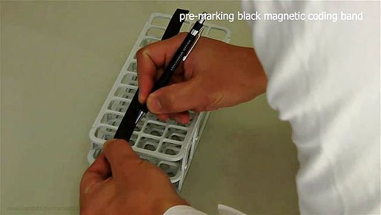
We have developed a new method, which should eliminate such problems and make the programming easy for all types of tube racks.
positioning.
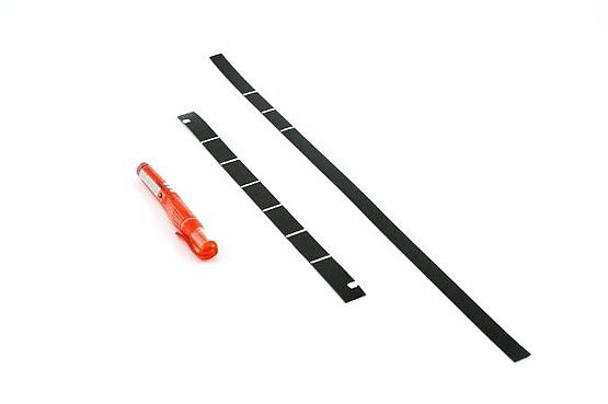
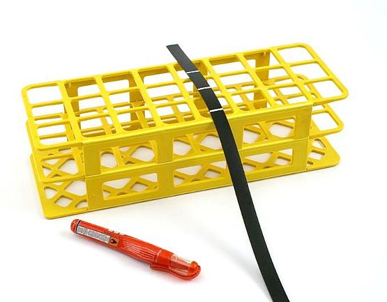
drawn on the black magnetic coding band as shown.
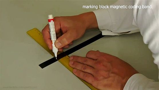
in a similar way. If you wish to switch off the collector automatically
after the last row, draw the last line broader (approx. 1 cm)
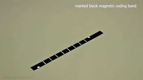
The white lines should be about 2 mm broad and full-length. These lines are detected by the photodetectors of the OMNICOLL fraction collector and the fraction collector stops at these positions. The actual fraction position is about 1 mm after the first edge of the white lines.
The beginning and end signals (at Figure 3.1-3) determine at the same time the position of the first and the last fraction in the row. The fraction position is about 2 mm after the first edge of the white line of the beginning and end stripes.
 | This simple coding principle allows the use of any tube racks and fraction stands or other recipients like bottles, 96-well plates, vials, etc. with the LAMBDA OMNICOLL fraction collector and sampler. |
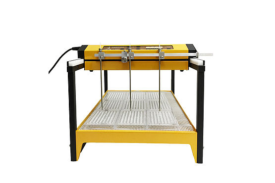
3.2 Ready to use Fraction collector with the supplied tube racks
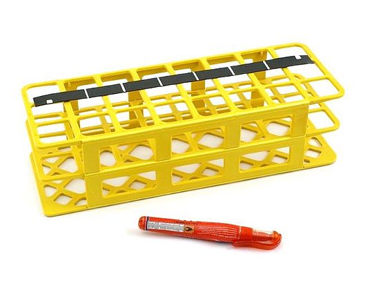
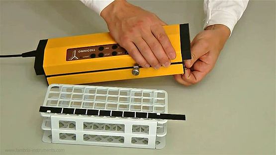
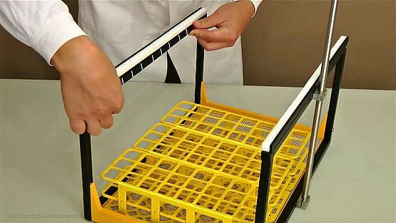
The magnetic coding bands programmed with white lines for the desired tube racks are provided with the OMNICOLL Fraction collector.
 | Place the magnetic coding strip strictly horizontally into the corresponding X-axis slot! Otherwise, the optical detectors could be damaged. |

OMNICOLL control unit as shown.
.
band into the X-axis holder.
desired slot of the control unit, with the white coding stripes facing up.
3.3 Programming the OMNICOLL for any tube racks or recipients
3.3.1 Coding X-axis for tube distance in row
Measure the distance between the tube centres of the desired rack and choose the number of fractions in a row.
| The beginning and end signals at the lower or upper edge of the coding band informs the microprocessor whether the arm of the control unit is on right or left. |
.

.
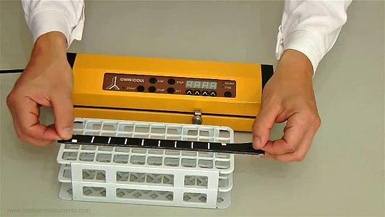
3.3.2 Coding Y-axis for row distance
Measure the distance between rows. When several tube racks are used, pay attention to difference in distance between the last row of the first rack and the first row of the second rack.
Measure the distance between rows. When several tube racks are used, pay attention to difference in distance between the last row of the first rack and the first row of the second rack.
If the fraction collection should be stopped at the last row, then make the last line broader (approximately 1 cm thick). This functions as the stop signal.
Since the coding band is kept in place by magnetic force, it can be easily positioned.
The first row line of the Y-axis should be ca 10 cm from the front.
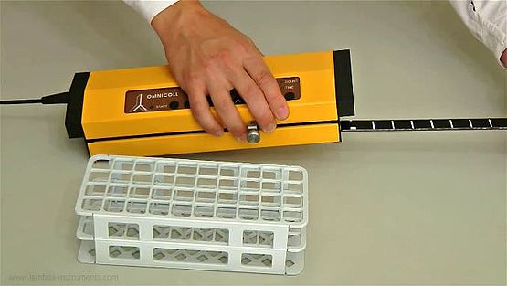
| When the control unit is placed in the starting position on the front of the frame, the photoelectric detector on the left side of the control unit must be situated before the first line. Otherwise the control unit will stop at the position of the next row. |
metal frame just under the gear bar.
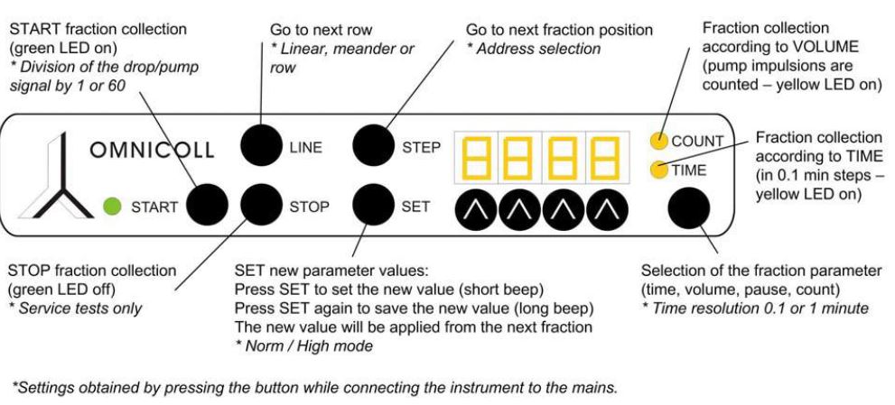
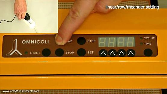
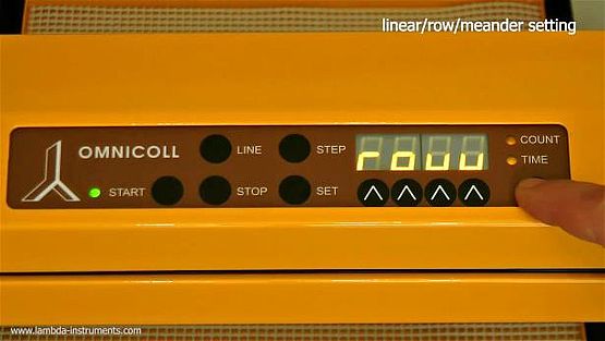
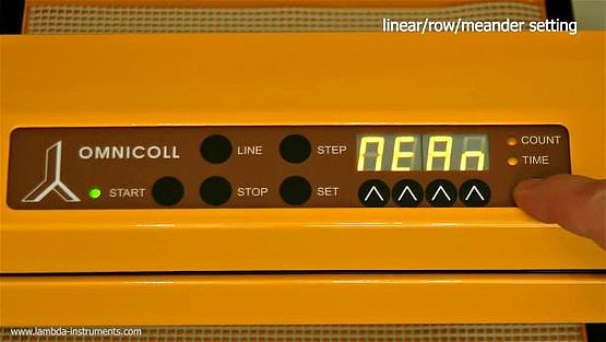
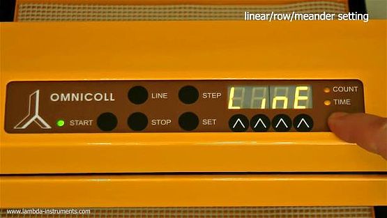
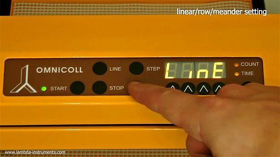
3.4.1 Selection of linear, meander-like or row collection
The LAMBDA OMNICOLL fraction collector-sampler allows the following operation modes:
Line: | The fractions are collected from the left to the right. After the last fraction of the row, the collecting arm moves to the left to the first position of the next row. |
|---|---|
| Meander: | The fractions are taken alternatively from the left to the right and in the following row from the right to the left and so forth. |
| Row: | The collecting arm does not move within the row. The collector moves only from row to row. This collection mode is mainly used in the simultaneous (multi-channel) fraction collection mode. |
In the row mode, the position of the fraction collecting arm can be adjusted by using the STEP button.
| | A small difference in the fraction positions with respect to the tube centres may occur between fractions taken in opposite collection directions. If the fraction lines are not too broad (about 2 mm), this difference in position is of approx. 1 mm |
.
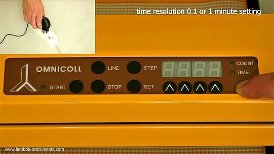
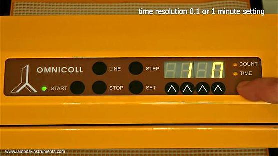
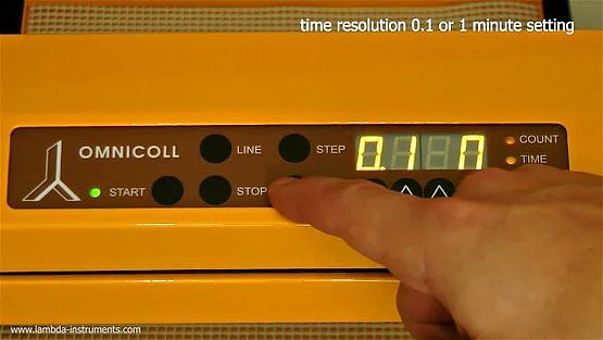
3.4.2 Time resolution (0.1 or 1 minute)
The time resolution of the OMNICOLL fraction collector can be selected in the following way:

.
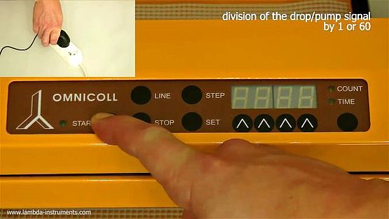
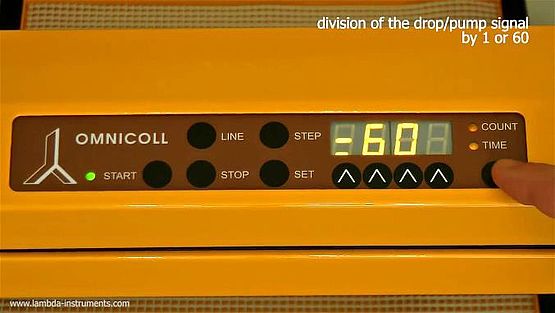
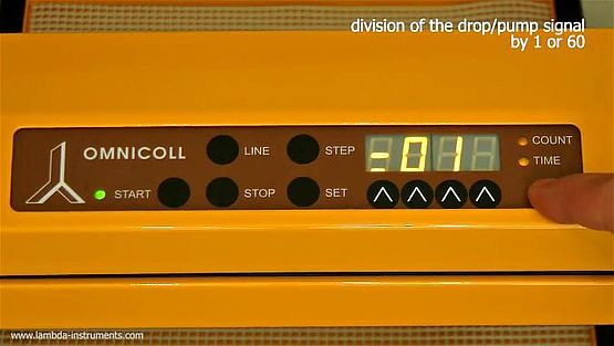
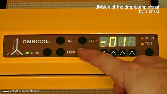
3.4.3 Drops and count divider (Division co-efficient)
This function allows increasing considerably (by 60 times) the volume of fractions either using a drop counter (art. no. 6926) or motor impulsions counter (counts).
The divider can be set either to divide by one or divide by 60. In the first setting, every drop and every impulsion of motor are counted. In the second setting, sixty drops or impulsions give just one signal.
The volume of fractions can be also varied by the selection of tubing of internal diameters from 0.5 to 4 mm, when constant volume fractions are collected by counting pump impulsions (in “COUN” operation mode – COUNT LED is on, refer section 3.5)
.
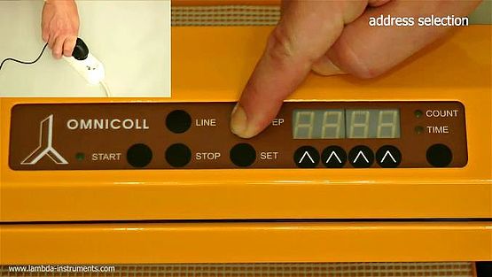
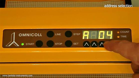
3.4.4 Address selection (for PC control)
When the OMNICOLL fraction collector and sampler has been equipped with the optional RS-232 interface, it can be controlled digitally, e.g. from a PC.


3.5 Fraction collection according to the volume
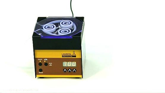
If you use the OMNICOLL fraction collector together with LAMBDA peristaltic pumps PRECIFLOW, MULTIFLOW, HIFLOW, MAXIFLOW or MEGAFLOW, you can take fractions of precise volume (from 0.05 to 500 ml or 0.6 to 30 litres per fraction).
The heart of these pumps is a stepping motor or BLDC motor, controlled by a generator of electric impulses (microprocessor). After each impulse, the pump motor moves by one step. This movement displaces a very small and precise volume of liquid.
The collector counts these impulses and thus makes it possible to deliver an exact volume of liquid for each fraction. This method is an attractive alternative to the old drop counting procedure, where the volume is affected by the viscosity, surface tension etc. of the respective liquid.
Since the diameter of the tubing used in the peristaltic pumps affects the speed of the flow (flow rate), the pump has to be calibrated before use in order to establish the relation between the count number and the delivered liquid volume.
It is also possible to synchronize OMNICOLL fraction collector with third-party multi-channel or single channel peristaltic pumps (e.g.: Cole parmer, Ismatec, Flexicon, etc.). We can offer customized remote control cable and communication module for pump switching and RS-232 connection (Art. No.: 6911) for the desired peristaltic pump connection.
3.6 Calibration of the peristaltic pump and the OMNICOLL
The LAMBDA peristaltic pump is connected to the OMNICOLL fraction collector via the remote control cable (Art. No. 4810-s) and the communication module box (Art. No. 6911 or Art. No. 6929). The plug-in power supply is also connected to this connection box. (It is impossible to make a wrong connection because the connectors will not fit to the wrong sockets).
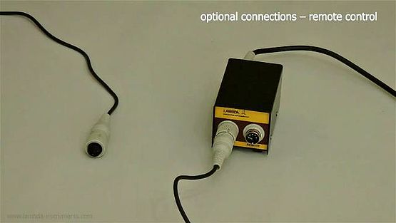
to the communication module box.
(the COUNT LED will be switched ON)

.
(e.g. 700), choose the pump rotation direction and switch the
pump ON.
Measure the volume of this fraction. This volume corresponds to the pre-set count number.
From this ratio (volume/count number) you can easily calculate the count number corresponding to the desired fraction volume.
| Since tubing of 0.5 to 4 mm of internal diameter (with a tubing wall thickness ~1 mm) can be used in the LAMBDA peristaltic pumps, the fraction volume can be selected in a wide range. For example, when tubing with an internal diameter of 3 mm is used, then one count corresponds approximately to one drop. |
3.7 Fraction collection with a time interval in-between fractions (“high”)
LAMBDA OMNICOLL fraction collector and sampler could be used for the collection of samples with a time interval between consecutive fractions varying between 0.1 min and 16.6 hours (999.9 min) or 1 min and 166 hours (9999 min).
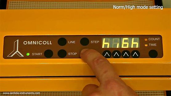
This is particularly useful during fermentations and other biological and chemical processes. For this application, switch the microprocessor of the control unit to the “high” mode.
Selecting the high mode:
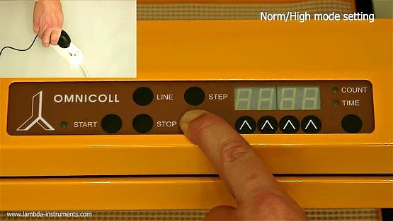
the plug-in power supply to the mains.
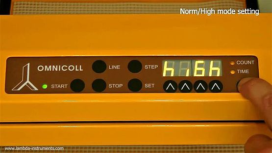
mode.
(long beep signal).
In the “high” mode you can successively select the parameters TIME, COUNT, PAUSE and NUMBER by pressing the COUNT/TIME button.
After selection of the parameter with the COUNT/TIME button, press the SET button.
After a short beep the name of the parameter will appear during one second, followed by last used value of the parameter.
You can change this value by means of the four buttons Λ Λ Λ Λ under the display. Press the button SET to confirm the new value (long beep).
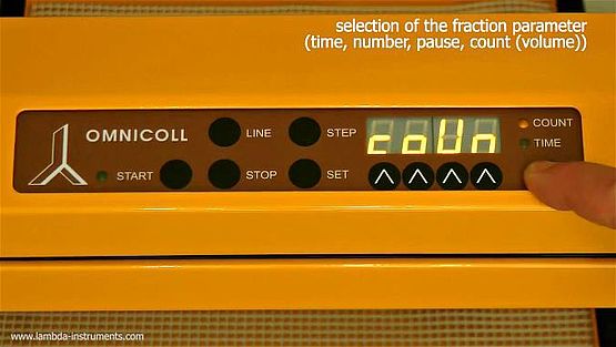
(volume).
[Count LED: ON;
Time LED: OFF;
Display: coUn]
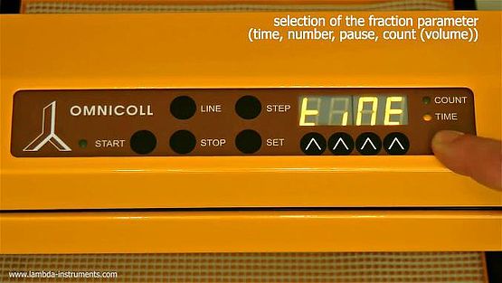
perform the program for a desired time.
[Count LED: OFF;
Time LED: ON;
Display: tiMe]
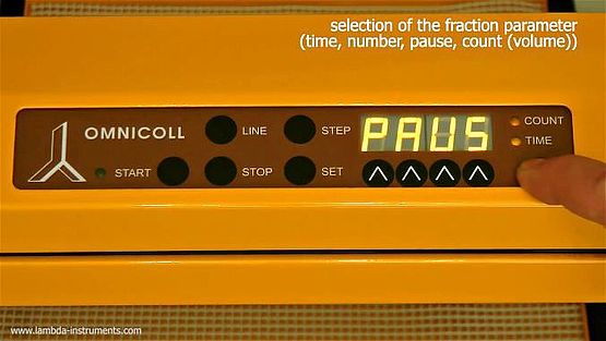
for introducing pauses in the program.
[Count LED: ON;
Time LED: ON;
Display: PAUS]
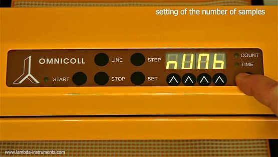
for collecting a number of samples.
[Count LED: OFF;
Time LED: OFF;
Display: nUMb]
After setting of the parameters, the fraction collection is started by pressing the START button.
The collector will take the number of samples as programmed under the NUMBER setting and will stop for the time programmed under the PAUSE setting. This cycle will go on until a STOP signal will be encountered. The LAMBDA peristaltic pump is activated automatically only during fraction collection.
| When the fraction collection is controlled from the panel (i.e. not by remote control signal) the fraction collector will collect the number of fractions/samples introduced in the parameter NUMB of duration TIME or volume COUNT (if a drop counter or LAMBDA pumps are used), followed by the PAUSE, if a PAUSE was set. |
Then, the fraction collector will repeat this till the STOP signal is encountered (i.e. STOP is pressed or the fraction collector is stopped by the end magnet). This collection mode allows for e.g. a line washing step before the relevant fraction is taken.
| If operated by external (analog) remote control signal, the fraction collector will take the set number of fractions/samples of duration TIME or volume COUNT (if a drop counter or LAMBDA pumps are used), and will then stop till the reception of a new external remote control signal. |
The parameter PAUSE is ignored in this operation mode.
Such a collection mode could be useful for taking of fractions/samples in a process where an alarm situation of a selected process parameter has occurred and the samples can be used for further analysis.
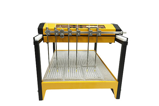
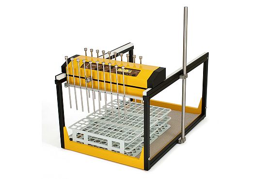
3.8 Multi-channel fraction collection – multiple stream sampling
LAMBDA OMNICOLL fraction collector and auto-sampler can be used for all kinds of chromatography such as normal or low pressure chromatography. It is also suitable for medium pressure chromatography sometimes called FPLC (Fast Protein Liquid Chromatography) or high pressure liquid chromatography (HPLC), also referred to as high performance liquid chromatography.
An interesting property of the LAMBDA OMNICOLL fraction collector is the possibility to collect simultaneously the streams of many chromatographic columns.
Multi-stream assembly is available for 2 to 18 or even more effluents of multiple chromatography columns. The multi-channel fraction collection configuration can also be customized for low volume recipients like 96-well plates.
In the number of simultaneous chromatographic streams the OMNICOLL is not outperformed by any other fraction collector on the market.
This multi-stream assembly is technically very simple and polyvalent. It allows an easy adaptation of various experimental needs directly by the user.
For more information about the multiple stream mounting, please do not hesitate to contact us at support@lambda-instruments.com
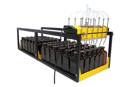
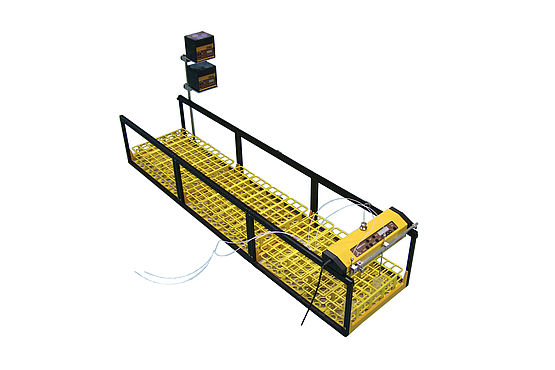
3.9 How to increase the capacity of the fraction collector?
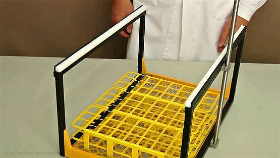
Since several lower parts of the collector can be coupled together, the capacity of the collector can be increased many times.
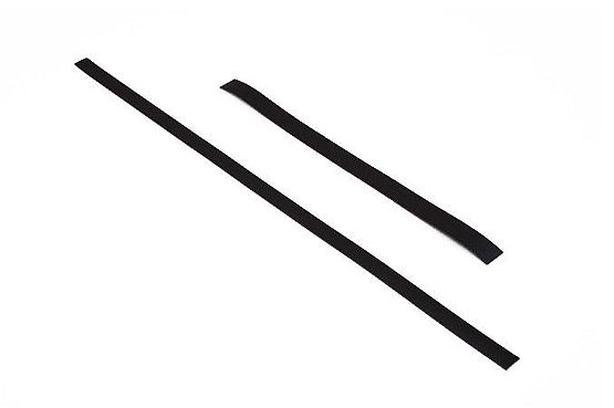
The control unit can move freely from one lower unit to the other on the gear rails. Only two rectangular coupling bars are needed to keep two units together.
- Remove the two blind bars from the rear side of the frame of the first lower part unit and the front side of the second lower part unit. Insert the coupling bars (Art. No. 6912) on their place and fix with the four bolts.
- Be aware that you must remove the fixed stop signal from the first frame unit and place it onto the next one. You may also use the magnetic stop contact.
- Make sure that nothing will block the movement of the control unit during the fraction collection.
The tube capacity of the LAMBDA OMNICOLL fraction collector and sampler can be easily increased by the addition of lower support. Virtually any number of capacity extensions can be added.