1. SETTING UP MASSFLOW GAS FLOW CONTROLLER / METER
The flow rate ranges depend on the MASSFLOW model and are as follows:
| MASSFLOW 5000 (controller or meter) (Art. No.: 8071 or 8071-s) | 0.00 to 5.00 l/min in 0.01 l/min steps |
|---|---|
| MASSFLOW 500 (controller or meter) (Art. No.: 8072 or 8072-s) | 0 to 500 ml/min in 1 ml/min steps |
| MASSFLOW 500 hs (high sensitivity)(meter only) (Art. No.: 8072-hs) | 0 to 99.9 ml/min in 0.1 ml/min steps & 100 to 500 ml/min in 1 ml/min steps (auto-range) |
1.1 Power Supply
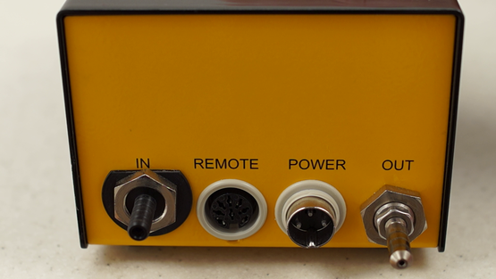
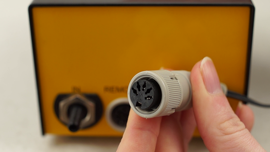
When used together with the LAMBDA MINIFOR laboratory bioreactor the MASSFLOW gas flow controller or meter is connected with the corresponding 8-pole cable to the “PUMP”- socket at the rear of the MINIFOR laboratory fermenter-bioreactor. The other side of the cable is plugged into the REMOTE-socket at the rear of the MASSFLOW.
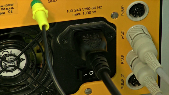
When used independently of the MINIFOR laboratory bioreactor-fermentor, a universal plug-in power supply (100-240 V AC/50-60 Hz, 12 VDC, 24 W) is used (art. no. 4821).
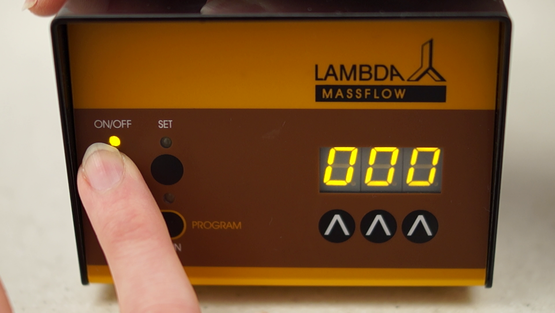
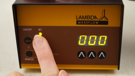
When the MASSFLOW is connected to the power supply, all LEDs and the display are lighted shortly. This allows a function control of all signal elements.
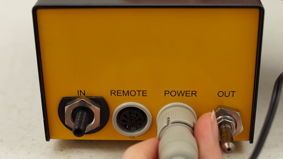
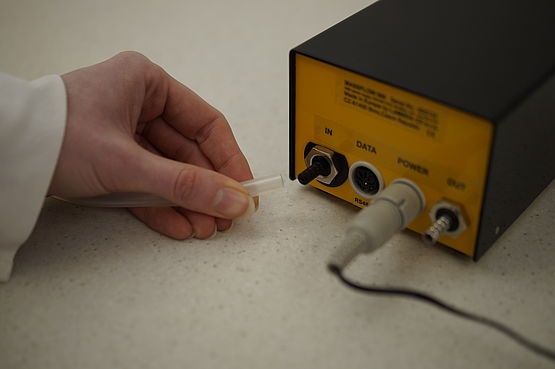
1.2 Gas input and output
The maximal gas pressure is 0.2 MPa (2 atm or 30 psig). Higher pressures will damage the instrument!
Fix the other tubing onto the gas OUT nozzle. Open the gas supply. The regulating valve is closed and no gas comes out from the output.