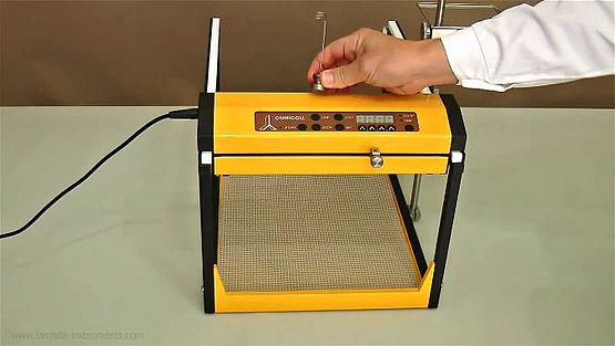
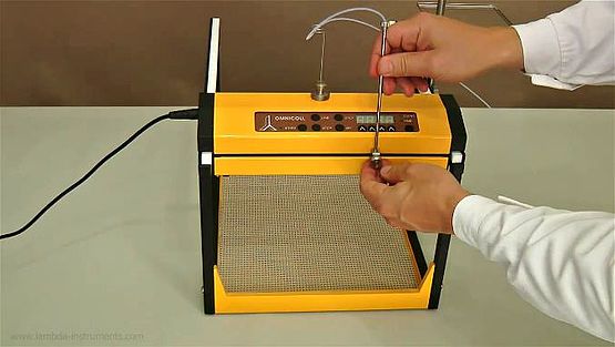
1.1 Assembling the fraction collector
1.2 Assembly of fraction collection tubing
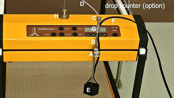
1.3 Connecting the drop-counter detector (optional)
1.1 Assembling the fraction collector
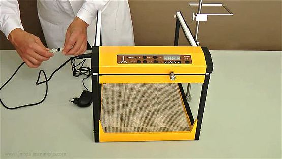
The setup of the fraction collection - sampler, LAMBDA OMNICOLL is very easy - a short video of the installation can be found at www.youtube.com/watch?v=33J9U_2-b-o
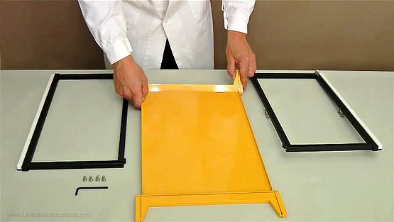
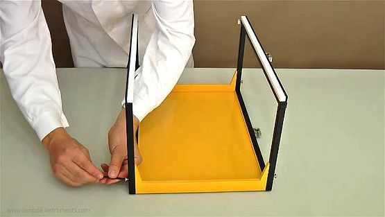
shorter side of the yellow support.

shorter side of the yellow support.
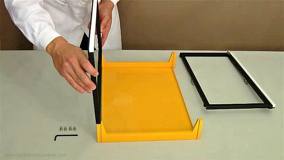
of the yellow supports
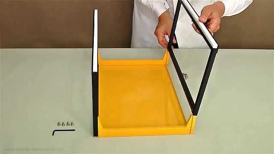
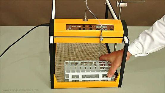
sides otherwise it will end up in blocking. The tub-sheet should not
slip out of the slots.
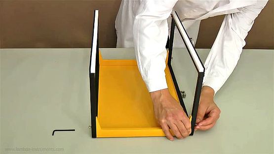
hexagonal key.
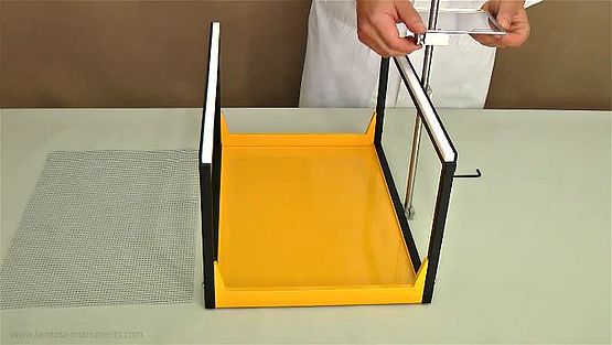
right side of the frame and fasten them with screws. If needed fix
the support plate on the metal.
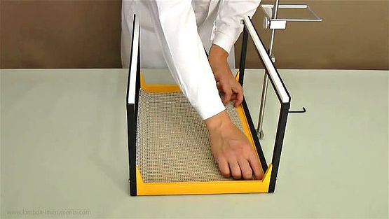
clean the mat from dust and dirt with a humid cloth. Make sure that
the mat is dry before use.
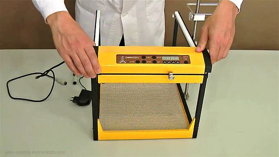
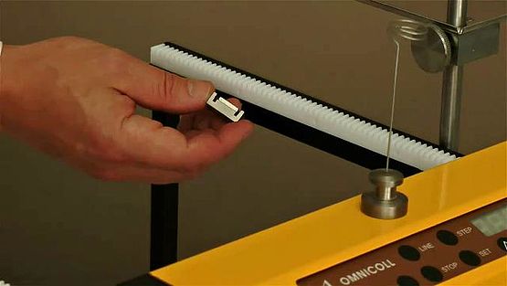
rails. The distance from the edge should be the same on the left
and right sides. The gear wheels of the control unit must engage
correctly in the gears of both rails. Be sure that nothing will disturb
the movement of the control unit during fractionation.
Available plug types: AU, EU, US, UK
of the frame to stop the fraction collection.
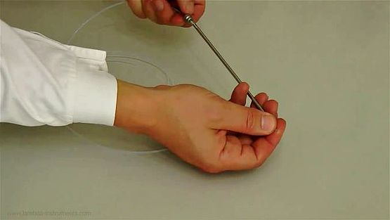
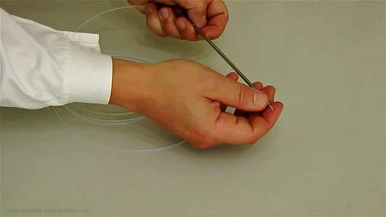
1.2 Assembly of fraction collection tubing
(a) PTFE tubing (external diameter 1.8 mm) |
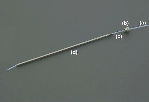
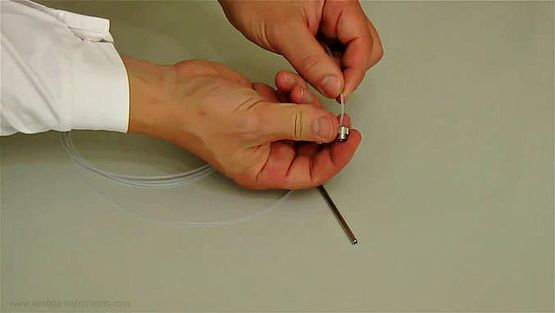
the pipe guide as shown.
sure a few mm (≈ 5mm) of PTFE tubing reach out of the tubing
guide so that the drops form only at the tip of PTFE tubing.
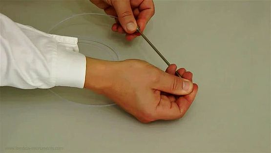
an extent that the PTFE tubing does not move freely inside the
tubing guide. Do not screw more strongly than necessary!
holder. Fix the tubing guide, with the help of the adjusting screw in
the holder, on the moving arm of the fraction collector at a convenient
distance above tubes.
1.3 Connecting the drop-counter detector (optional)
The drop counter is an optional device which could be obtained on request.
Fractionation can also be done according to the desired number of drops in the fraction collector using the drop-counter.
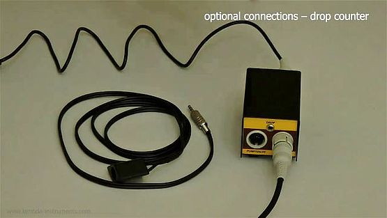
communication module (Art. No.: 6929)
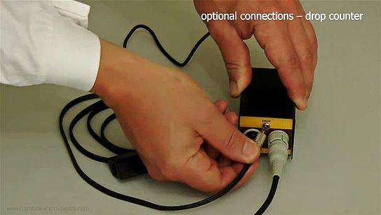
“DROP” socket of the communication module.
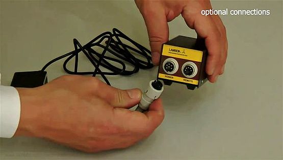
in the communication module.
.
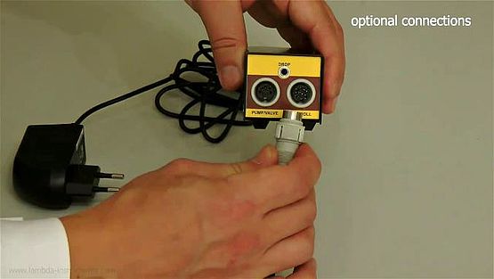
“OMNICOLL” socket in the communication module.
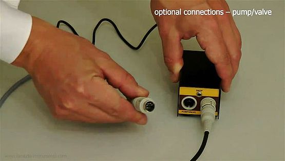
“PUMP/VALVE” socket in the communication module.