1.1. Pre-treatment of the dosing powder
1.2. Assembly of the LAMBDA DOSER
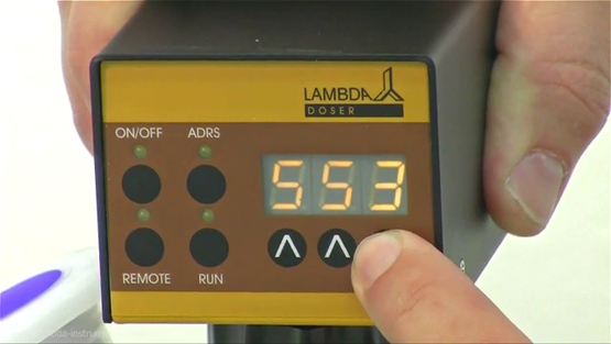
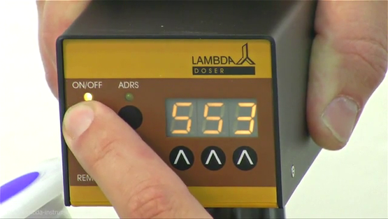
1.3. ON/OFF button
1.4. Setting of the dosing speed
1.5. Fast filling function
1.6. Use of the DOSER during reflux or under controlled atmosphere
1.7 FAS / SLO mode of HI-DOSER
1.1. Pre-treatment of the dosing powder
The dosing sample (powders, crystals, solids, etc.) has to be homogenous and free flowing. If this is not the case, they should be recrystallized, dried and sieved to remove the fines.
The free flow of difficult solids can be achieved by the addition of AEROSIL 200 or 974 at a concentration of 0.1 to 2 %.
AEROSIL is super finely dispersed pure SiO2. Its particles cover the surface of the crystals and make it free flowing. AEROSIL is non-toxic, chemically inert and can be removed by filtration. It can be obtained at a low price from us.
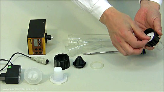
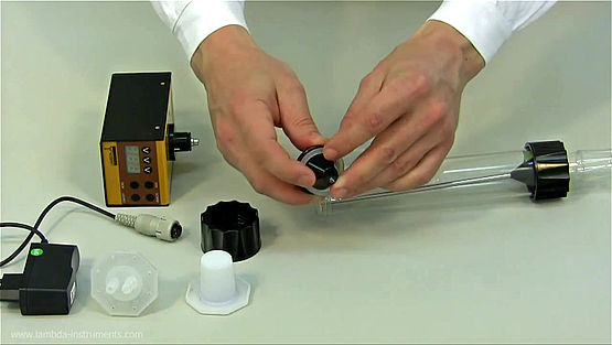
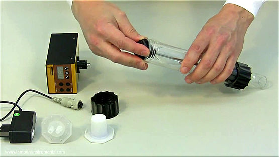
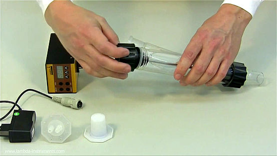
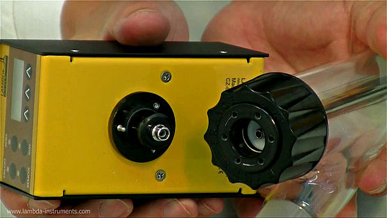
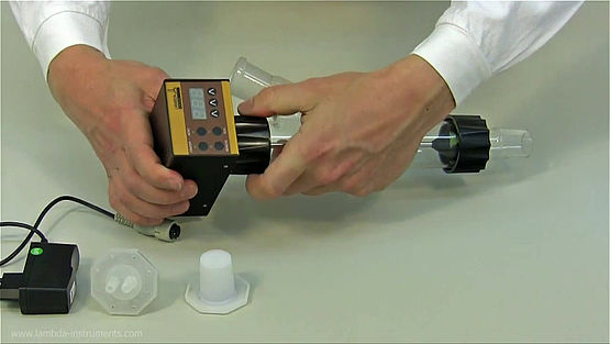
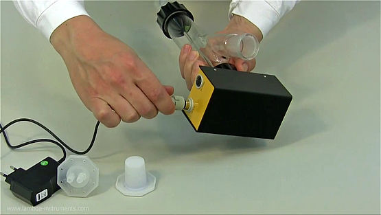
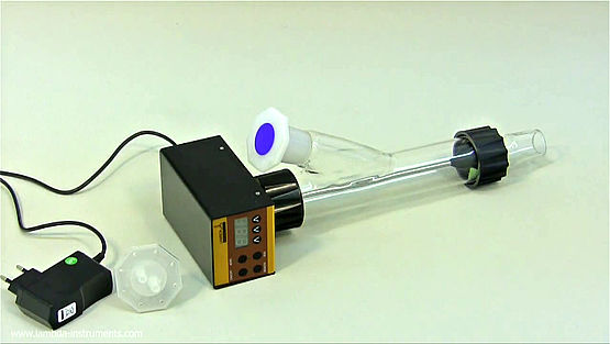
1.2 Assembly of the LAMBDA DOSER and HI-DOSER
The picture below depicts the parts of the powder feeding instrument, DOSER 0.2 L:
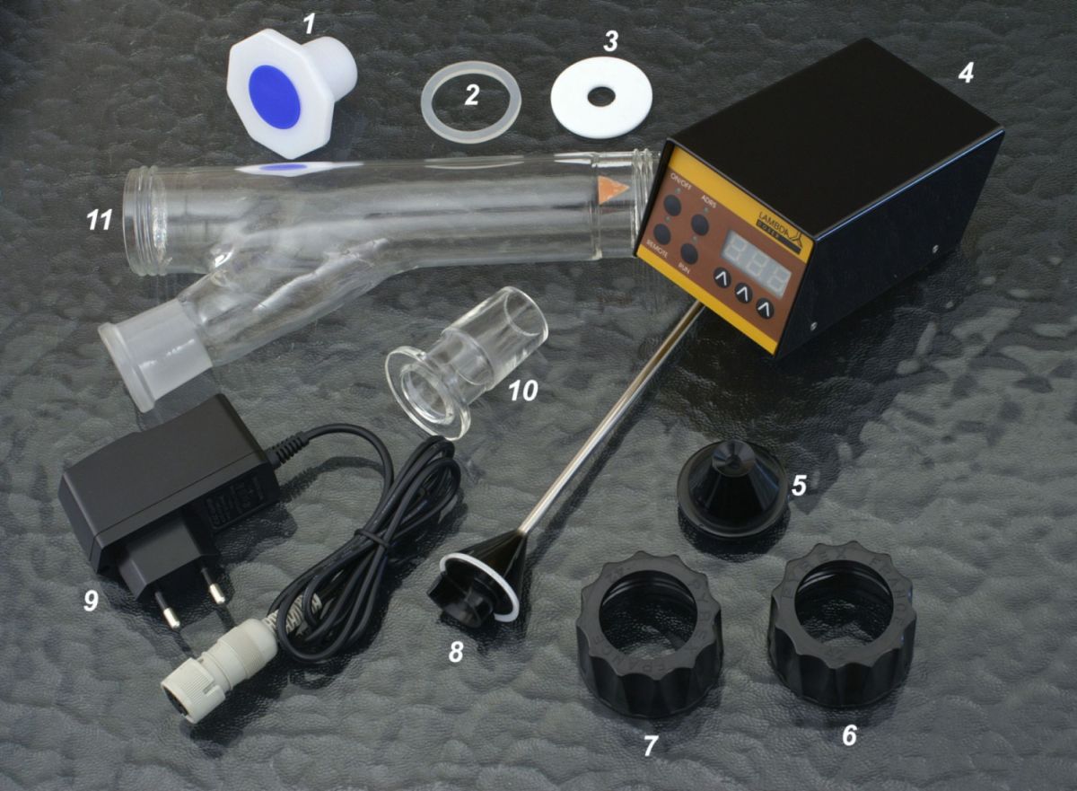
| S. No. | Name of the parts | Art. No. |
|---|---|---|
| 1 | Blind plug | 5808-b |
| 2 | Rubber sealing disc | 5806 |
| 3 | Teflon disc | 5803 |
| 4 | Control unit | 5809 |
| 5 | Centering part | 5807 |
| 6 & 7 | Screw cap SVL 42 | 5802 |
| 8 | Distributor (standard) | 5804 |
| 9 | Plug-in power supply (12 V / 12 W) [Plug type: UK, US, EU, AU] | 4820 |
| 10 | Glass adaptor with ground NS 29/32 fitting | 5801 |
| 11 | Glass vessel with side arm (approx. 0.2 l) | 5810 |
The setup of the powder dispensing system, LAMBDA DOSER and HI-DOSER is very easy - a short video of the installation of DOSER 0.2 L could be found at www.youtube.com/watch?v=eYE8CrPlvd8
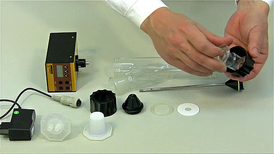
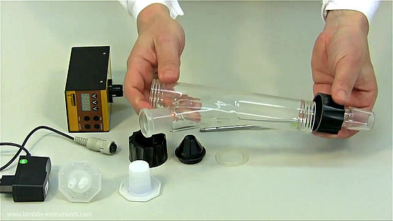
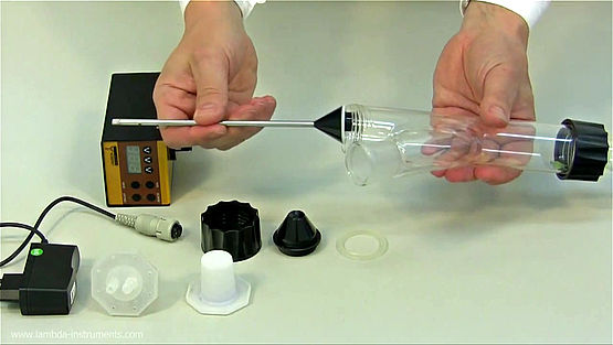
.
By pressing the ON/OFF button, the powder feeding instrument (DOSER / HI-DOSER) is switched ON or OFF. The internal memory will show the last used speed and flow direction setting.
1.4 Setting of the dosing speed
The powder dosing rates depend on the powder properties and the DOSER or HI-DOSER motor rotation speed.
The speed of powder addition is selected by the control buttons Λ Λ Λ under the LED display. The digital selection allows good reproducibility of the selected dosing rate.
Since specific densities of solid substances vary considerably, it is important to calibrate the DOSER or HI-DOSER before starting the powder dosing.
For this, the amount of substance delivered during a certain time period is measured (e.g. for 1 minute with speed setting 500). The speed of rotation of the distributor increases progressively with the speed setting value. Using this information, the speed setting corresponding to the desired flow rate of the solid substance can be calculated easily (rule of three).
The dosing of the powdery substance is started by pressing the ON/OFF button. The corresponding LED indicates that powder dosing is in progress.
1.5 Fast filling function
If the ADRS button is pressed continuously for about 2 seconds, the distributor will rotate at its maximum speed.
After releasing the ADRS button, the powder dispensing is stopped. This function is useful for fast filling of a recipient or emptying of the glass vessel of the LAMBDA DOSER or HI-DOSER at the end of powder dosing operation.
The ADRS (“HOLD=MAX”) function can also be used, even if the ON/OFF button has not been pressed.
1.6 Use of the DOSER and HI-DOSER during reflux or under controlled atmosphere
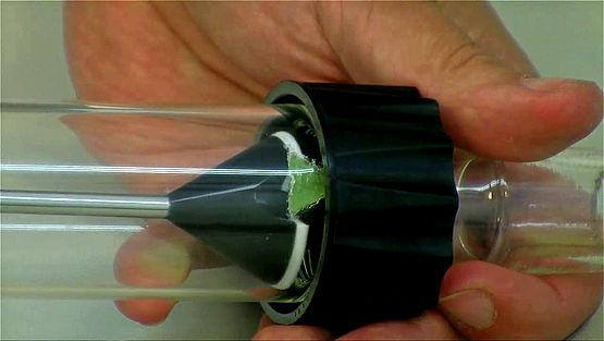
Vapours of boiling solvents can penetrate into the lower part of the DOSER or HI-DOSER and condense. The condensation disturbs the flow of the solid, which can be prevented by purging a light stream of air or other convenient gas through the glass vessel of DOSER or HI-DOSER. The vapours are displaced and cannot disturb the dosing.
The gas can be introduced into the vessel by a special stopper fitted with tubing. We deliver a polyethylene stopper for this purpose. However, any fitting, compatible with NS 29/32 ground fittings (e.g. SVL threaded fittings which can be adapted to several tubing diameters are excellent).
The slight gas stream passes through the hollow axis of the distributor and the lower part of the DOSER or HI-DOSER vessel. The stream and pressure of the gas must be carefully controlled to prevent compression of the solid substance during the dosing process.
Since the DOSER and HI-DOSER units are airtight, it can also be used to work under controlled atmosphere (N2, Ar, etc.). The DOSER and HI-DOSER withstands a pressure of ± 0.05 MPa. The airtight dosing unit is particularly useful while working with oxygen sensitive or hygroscopic substances. In this case, manual dosing is very difficult.
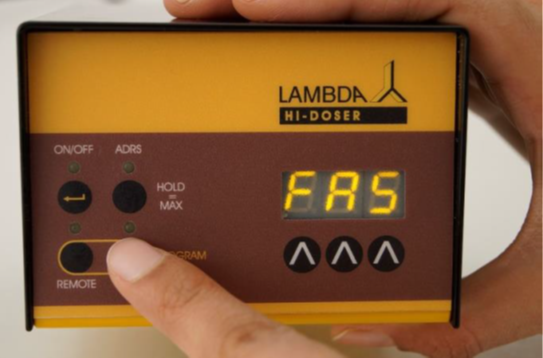
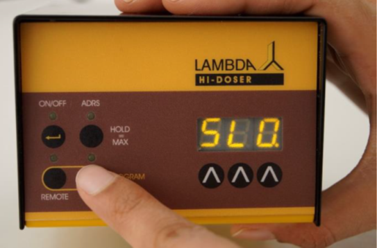
1.7 FAS / SLO mode of HI-DOSER
The HI-DOSER powder dosing instrument allows to dose the powders at two speed settings: SLO. = slow and FAS = fast.
In the standard mode (FAS), the flow rate of the speed setting 0 to 999 ranges from approx. 250 mg/min to 250 g/min for NaCl.
In the slow mode (SLO.), the flow rate of the speed setting 0 to 999 ranges from approx. 60 mg/min to 60 g/min for NaCl. The slow mode is indicated by the dot in the last position on the digital display.
The fast filling function ADRS (HOLD = MAX) is the same for both speed ranges.
Remark: During the RS-communication, only the value shown on the display is transferred, but not the speed range (mode). If the PUMP-FLOW INTEGRATOR is activated (optional), a single integrator step is independent of the set speed range (mode).