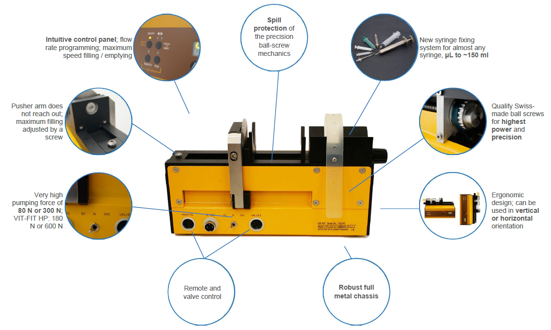
1.1 Parts of Syringe Pump
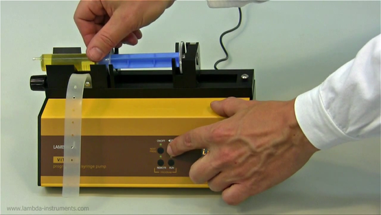
1.2 Insertion of the Syringe
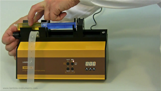
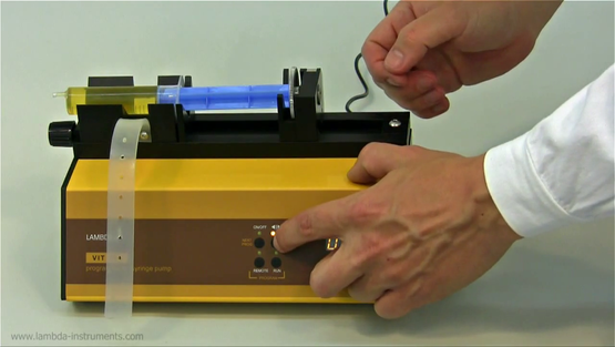
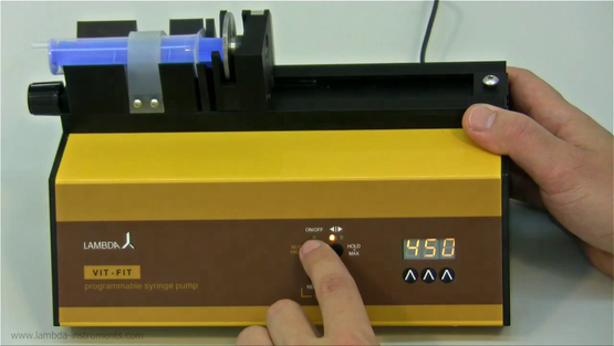
1.3 ON/OFF button
1.4 Setting up the flow rate
1.5 Choosing the flow direction
1.6 Fast pusher movement function
1.7 Reduction of the pumping force
1.8 Valve Control
1.1 Parts of Syringe Pump
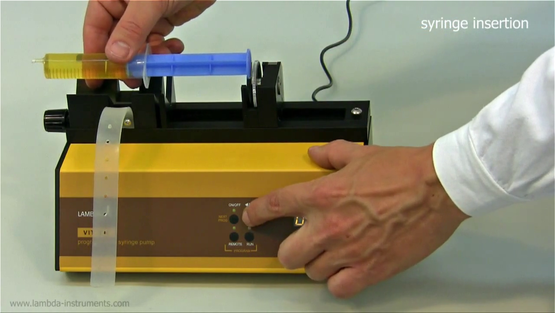
1.2 Insertion of the Syringe
A short video of the installation could be found at www.youtube.com/watch?v=SgJb2Ag6lG8
.
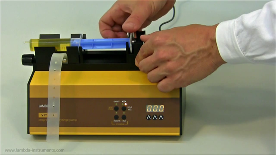
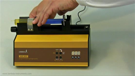
Select the direction (button ◄|►) and press the ON/OFF button to move the syringe plunger along the start position and displace the bubbles in the line, if any. The syringe pump is now ready for use.
Remark: The maximum filling position of the pusher can be blocked mechanically by a screw in the fixing dice.
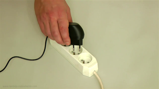
1.3 ON/OFF button
By pressing the ON/OFF button the pump is switched on or off. The internal memory will show the last used speed and flow direction setting.
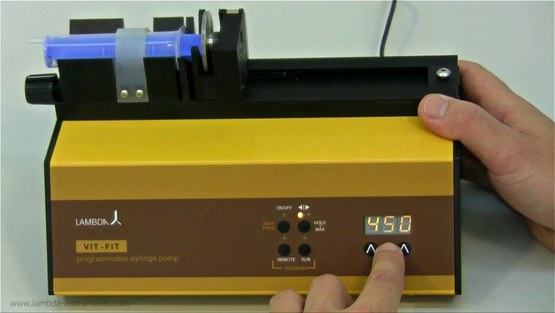
1.4 Setting up the flow rate
The flow rates of any liquid dispensed by syringe and infusion pumps depend on the internal diameter of the used syringes and the syringe pump pusher speed.
The VIT-FIT syringe pump has been constructed for syringes up to 150 ml. Almost any available type of syringe (metal, glass and plastic syringes) can be used with the VIT-FIT infusion pump.
The speed of motor is selected by the control buttons Λ Λ Λ under the LED display.
The best way to correlate the flow rate obtained with any syringe is to make a preliminary calibration, in which the pump is allowed to pump the liquid over a certain time with a selected speed setting (e.g. for 1 minute with speed setting 500). Then the weight or volume of the pumped sample is measured. Using this information the speed setting corresponding to the desired flow rate can be calculated easily (rule of three).
1.5 Choosing the flow direction
The direction of the pusher movement can be selected by the ◄|► button. The corresponding direction LED will be on.
1.6 Fast pusher movement function
Keep the direction ◄|► button pressed constantly for about 2 seconds. This will produce fast movement of the pusher in the direction indicated by the LED. The pusher will move in the selected direction at maximum speed. This “HOLD=MAX” function can be used even though the ON/OFF button has not been pressed.
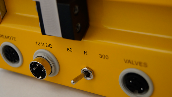
1.7 Reduction of the pumping force
The mechanics of the LAMBDA VIT-FIT syringe pump develops a force of up to 300 N (or 600 N for the high-pressure syringe pump model VIT-FIT HP). This is very appreciated by users who need to operate with high pressures. However, such a force may be too large, especially when small syringes are used. Therefore, the force setting can be limited to 80 N (or 160 N for the VIT-FIT HP) by the switch at the rear of the syringe pump.
1.8 Valve Control
The VIT-FIT infusion pump is equipped with two outputs for valves. It supplies a DC signal (12 V/1 A) for the control of valves. When, one output is on the other output is off. This allows cyclical operation of the syringe pump. For the detailed connection scheme refer section 7.4 and figure 7-3.