1 Setting up the Peristaltic Pump
A short video of the peristaltic pump installation can be viewed online at www.lambda-instruments.com/peristaltic-pumps/#video.
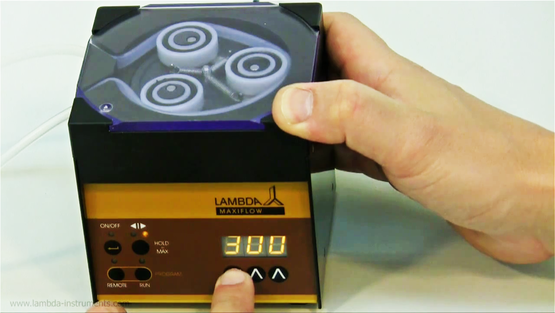
1.1 Tubing Insertion
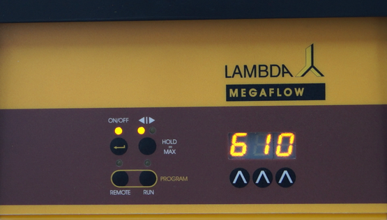
1.2 ON/OFF button
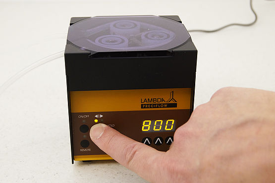
1.3 Setting up the flow rate
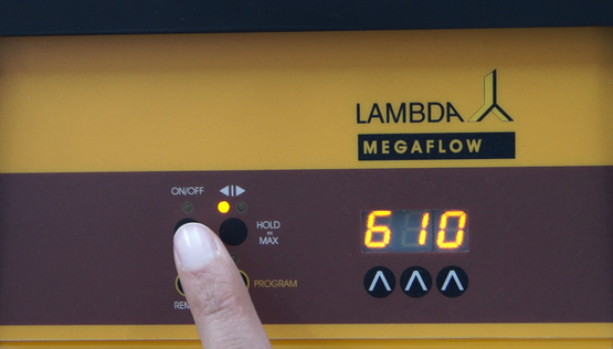
1.4 Choosing flow direction
1.5 Fast filling or emptying the line
1.6 FAS / SLO mode of MEGAFLOW pump
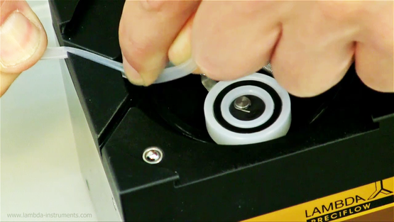
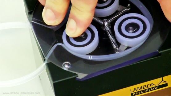
1.1 Tubing Insertion
 | While inserting the tubing on the pump head, care should be taken not to get the fingers clamped by the rollers. | |
|---|---|---|
 | Press the tubing to the bottom of slot, when inserting and fixing the pump tubing on the pump head. The correct position of the tubing is important, especially in-case of thin tubing. |
.
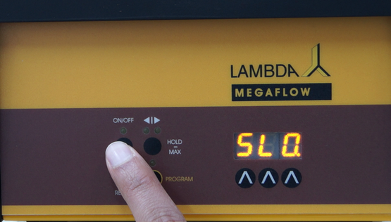
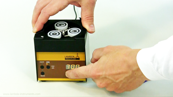
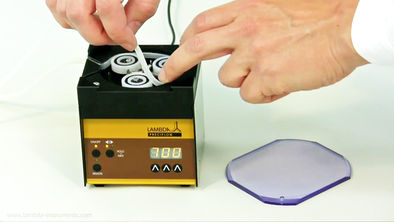
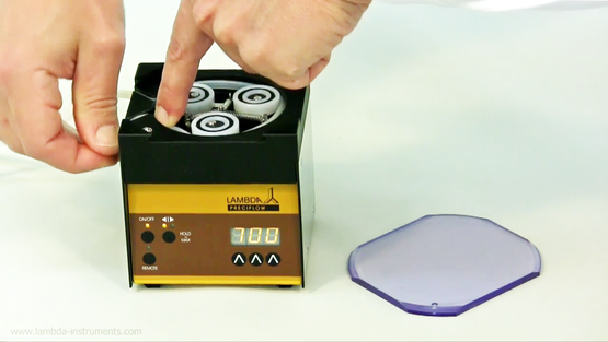
1.2 ON/OFF button
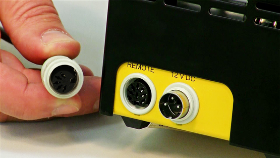
By pressing the ON/OFF button, the peristaltic pump is switched on or off. The internal memory will show the last used speed and flow direction setting.
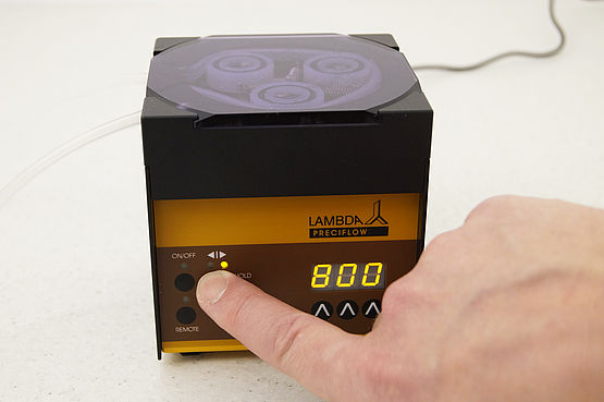
1.3 Setting up the flow rate
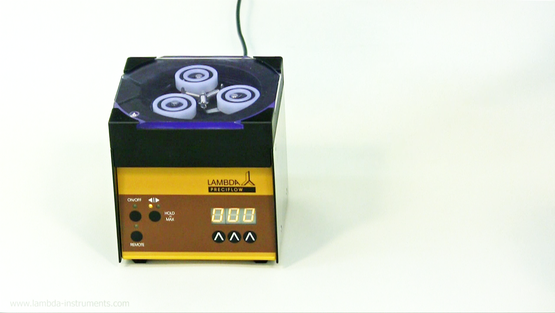
The flow rates delivered by peristaltic pumps depend on the internal diameter of the tubing and the pump rotation speed. The speed of rotation can be selected by the control buttons Λ Λ Λ under the LED display.
Pump tubing diameter
PRECIFLOW, MULTIFLOW, HiLFOW and MAXIFLOW peristaltic pumps from LAMBDA Laboratory Instruments are designed for pump tubing with an internal diameter range of 0.5 to 4 mm with tubing wall thickness of approximately 1 mm.
The best results are obtained with silicone tubing, but tubing made from other materials with similar elasticity as that of silicone tubing can also be used (i.e. Shore hardness 50-60).
LAMBDA MEGAFLOW peristaltic pumps are suitable for pump tubing with an internal diameter range of 1 to 8 mm with tubing wall thickness of approximately 2 mm.
Setting pump speed
With the control buttons Λ Λ Λ below the LED display the motor speed is selected. The speed setting from 0 to 999 corresponds to the velocity of the movement of the motor.
The best way to correlate the flow rate obtained with the respective tubing is to make a preliminary calibration, in which the pump is allowed to pump the liquid over a certain time with a selected speed setting (e.g. for 1 minute with speed setting 500). Then, the volume (refer section 3.1) or weight (refer section 3.2) of the pumped sample are measured. Using this information, the speed setting corresponding to the desired flow rate can be calculated easily (by rule of three).
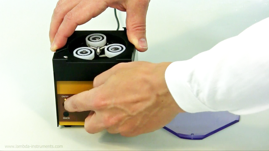
The direction of the pump rotation can be selected by the ◄Ι► button, clockwise or anti-clockwise. The corresponding direction LED diode will be ON.
If possible use the clockwise rotation of the tubing pump. This results in lower friction and the pressure of the liquid (approx. 0.18 MPa). If a higher pressure is required (up to 0.2 MPa), use the counter-clockwise rotation.
1.5 Fast filling or emptying the line
By pressing the direction button ◄|► for approx. 2 seconds, the peristaltic pump will rotate at a maximum speed in the direction indicated by the LED.
After releasing the direction button, the pump stops pumping the liquid.
This "HOLD = MAX" function is used to fill the tubing before the actual dosing or to empty the tubing line at the end of the lab experiment.
The "HOLD = MAX" function can also be used even if ON/OFF button has not been pressed.
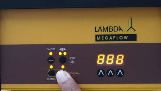
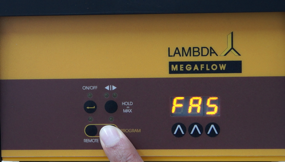
1.6 FAS / SLO mode of MEGAFLOW pump
LAMBDA MEGAFLOW peristaltic pumps allows pumping the fluid at two speed ranges (modes):
- FAS = Fast mode, 0 - 60 L/h (standard mode)
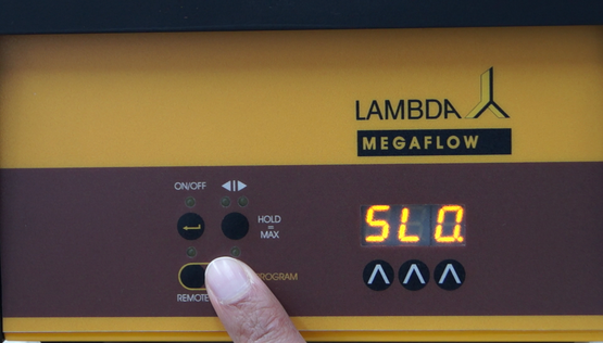
- SLO. = Slow mode, 0 - 12 L/h
In standard mode (FAS), motor speed setting from 0 to 999 covers the flow range from 0 to 60,000 ml/h.
In slow mode (SLO.), motor speed setting from 0 to 999 covers the flow rate range from 0 to 12,000 ml/h
The slow mode is indicated by the dot in the last position on digital display of the pump.
The fast filling function ◄|► (HOLD = MAX) is the same for both speed ranges.
Remark: During the RS-communication, only the value shown on the display is transferred, but not the speed range (mode). If the PUMP-FLOW INTEGRATOR is activated (optional), a single integrator step is independent of the set speed range (mode).